Radiohead – yes, that British band – and metallurgy have some common. After work, you visit the local store to purchase some groceries. You put everything in that red plastic bag and return home. The bag is quite heavy, and the plastic handle digs into your skin, causing it to hurt. Finally, you reach your home, and your fingers return to their original color. Suddenly, you notice that the handle of the plastic bag has a different color than before, and its surface looks thinner than usual. You wonder what could have happened to the bag’s handle. You have just encountered the most „unwelcome” and, unfortunately, unavoidable phenomenon in thermal power plants: creep. Yep, just like that famous Radiohead song. The battle against creep requires creep-resistant steels…
Creep-resistant steels… Wait, what?
If we open any books or do some Google research, we would get a definition like this:
Time-dependent and irreversible plasticity under a fixed stress at an elevated temperature, often more than 0.4 Tm, where Tm is the absolute melting temperature.
So, what do we know?
- this is a slow, time-dependent process
- it is irreversible, which means something terrible is happening; we cannot undo it.
- this is a plasticity; my material would permanently deform. We know from the strength of materials that if something deforms, there is a high chance that the material will get thinner.
- The fixed stress indicates, there has to be some load.
- All of this happens at elevated temperatures.
Creep can occur at all temperatures above absolute zero because diffusion assists creep. The higher the temperature, the higher the diffusion speed and, therefore, the effect of creep. Creep has been associated with time-dependent plastic deformation at elevated temperatures, and here comes the 0.4Tm rule.
The formation of micro-cavities at grain boundaries has been an area of study since the 1970s, and it is now widely recognized and applied. The concept is based on the fact that the evolution of creep-resistant steels is associated with the formation of cavities before rupture. These cavities gradually grow into micro-cracks by interlinking and eventually lead to rupture. The size and the density of cavities increase as creep progresses from the secondary to the tertiary stage. Since cavity size is in the micron (μm=10-6m) range, they cannot be detected by conventional non-destructive techniques such as penetrant testing and ultrasonic testing, and metallographic investigation is required to identify them.
Creep in action
Figure 1 represents the steeps of creep fracture from the start till the rupture.
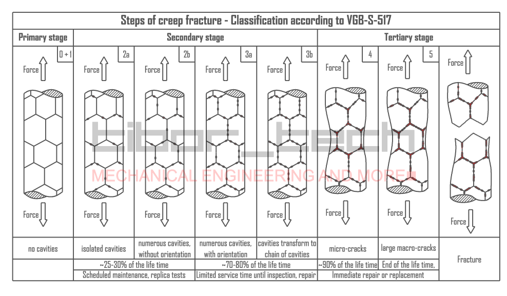
Failure due to cracking can be divided into three stages: crack initiation, crack propagation, and final failure of the component once the crack reaches a critical size. Therefore, life-assessment techniques aim to measure incipient damage, whether uniform or localized, before crack initiation, the speed at which cracks grow, and the critical crack size that will lead to final failure. The best way to determine the remaining lifetime is through metallographic methods.
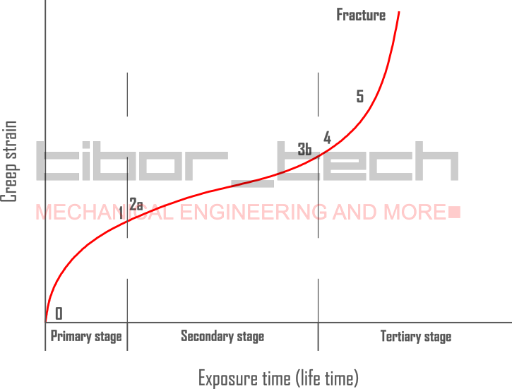
As a time-dependent process, we can have a better overview by using creep-strain-exposuretime diagrams – Figure 2:
The begins
What’s happening inside a thermal power plant? Our mission is to push the boundaries of thermal efficiency to their limits. Achieving this means working with high-pressure, high-temperature steam—knowledge that’s crucial for optimizing energy output. But with great pressure and temperature comes great stress! The steam exerts formidable loads on the inner walls of the pressure vessel, creating intense longitudinal and hoop stresses that challenge engineering integrity.
At the dawn of the 20th century, engineers realized that boosting efficiency was impossible without tackling creep degradation—the slow, destructive deformation under high temperatures and stresses. Thanks to continuous advances in metallurgy and steel production, we’ve dramatically elevated steam parameters from a modest 275°C/12 bar to an astonishing 620°C/300 bar.
Today, the quest continues. Cutting-edge R&D projects are racing forward to unlock even higher steam temperatures—aiming for 700°C, 760°C, or beyond! With the development of revolutionary Ni-based alloys, we’re on the brink of achieving steam conditions around ~334 bar and a scorching 800°C. This isn’t just progress; it’s a leap towards a new era of ultra-efficient, ultra-powerful energy generation!
Creep-resistant steels up to 2.25%Cr
Until the 1920s, using C-Mn, unalloyed structural steel for boiler applications was common practice. Steam parameters in these days have reached a maximum of 350°C and a pressure of about 15bar. As a safety precaution, material properties were tested at the operating temperature, which meant a hot tensile test was the only option with the given technical possibilities. In these short-term tests, it was impossible to identify the long-term effect of alloying elements on the creep strength of C-Mn steels.
In the 1920s, significant strides were made in understanding the behavior of ferritic steels and the impact of alloying elements at elevated temperatures. Among the various alloying concepts studied, one element stood out. Molybdenum (Mo) was a game-changer when introduced as an alloying element, significantly enhancing steel’s mechanical properties at elevated temperatures – Figure 3.
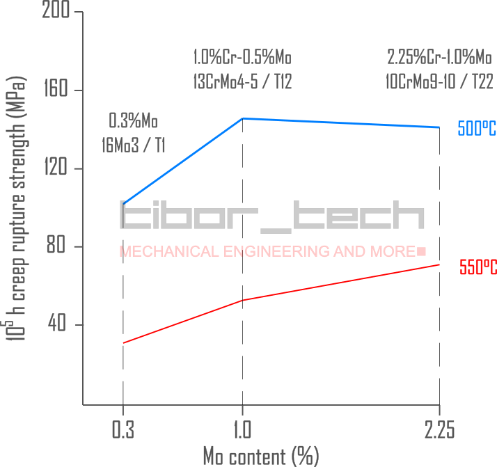
In 1933, in the US, the ASTM and ASME prepared a guideline on how to test structural materials for boiler applications at elevated temperatures. That was the first time a longer test time was requested: a 500-2000h test regime to determine the creep strain limits for a permanent creep strain of 0.01, 0.1, 1.0, and the ultimate creep rupture limit. Based on these test results, the long-term creep properties were extrapolated on a double-logarithmic scale up to 105h.
1st generation of creep-resistant steels
At this time, countless developments were running, mostly in individual steel workshops, without any coordinated effort. When a new alloy was discovered and tested, it was sold under the steel workshops’ brand name. Various alloying concepts were investigated, such as Cr, Mo, Ni, V, MnMo, MnSi, CrV, CrMnV, CrMoV, CrMo, and CrNiMo.
Mo alloyed steel raised the operating pressure to 35bar and the temperature to 450°C—Mo’s alloying effect results from solution hardening and Mo2C precipitation hardening of the ferritic structure. Following a logical progression, the Mo content was increased to 0.5-1.0%; a higher molybdenum level reduces creep ductility and graphitization at the service temperature.
In the 1940s, the next development phase was to combine chromium (Cr) with Mo to increase the operating temperature. Although the Cr-Mo alloying concept was known from armor development, it was only adopted in this decade. Various materials have been developed for boiler plates, piping, and tubing:
| Alloying system | ASME designation | EN designation | Maximum temperature [°C /°F] |
|---|---|---|---|
| 0.15%C-0.5%Mo | T1 | 16Mo3 | 425 / 800 |
| 0.13%C-1.25%Cr-0.5%Mo + Si | T11 | 13CrMo5-5 | 565 / 1050 |
| 0.13%C-1.0%Cr-0.5%Mo | T12 | 13CrMo4-5 | 590 / 1095 |
| 0.10%C-2.25%Cr-1.0%Mo | T22 | 10CrMo9-10 | 650 / 1200 |
Figure 4 shows the allowable stress for these 1st generation, low-alloyed steels:
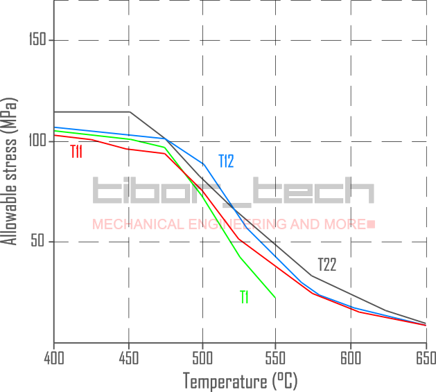
Microstructural investigations have been conducted as these materials have been used in service. The study showed that the 1.0%Cr-0.5%Mo alloy has different precipitations (M3C, M7C3, M3C, and M23C6) compared to the 2.25%Cr-1.0%Mo alloy, which has Mo2C and M23C6 precipitations.
2nd generation of creep-resistant steels
Early trials with vanadium (V) alloying were made in this decade. It was found that a 0.14%C-0.6%Mo with 0.3%V overperforms the higher alloyed 10CrMo9-10 materials. An extensive microstructural investigation was done to explain these findings. As a result, the newly discovered, fine-dispersed V4C3 precipitation alongside Mo2C showed higher thermal stability than the previously identified precipitations. As a significant drawback, this steel tended to develop cracks at the interstitially heated area in the welds’ heat-affected zone (Type IV cracks).
In the 1950s, the effect of trace elements, like phosphorus (P), became understood. The high P content (~0.03%) contributed to embrittlement. Improvements in the melting process helped increase service life and reduce P content. In the 1960s and 1980s, the classical T22 with V – called T22V -addition was used to achieve higher steam parameters in the water walls.
In 1984, Grade 91 (see below) was adopted in the ASME Code. The creep strength of this material at 600°C is roughly twice as great as that of the currently used T22 – Figure 5. Besides that, T22 was utilized up to 580°C, but the creep strength difference was too big.
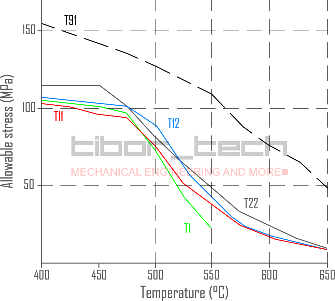
The engineers now had two options:
- Go with Grade 91 materials in the water wall as well
- Develop new materials within the low-alloyed steel family.
Using Grade 91 in a water wall would be challenging. This alloy only has a superior creep strength if the post-weld heat treatment (PWHT) is done correctly. However, applying extensive PWHT in the manufacturing was almost impossible due to the distortions of long but less stiff water-wall panels. As Grade 91 was the best choice, a new material was needed to meet the following requirements:
- It has similar creep strength and oxidation resistance as the steel
- Has an improved weldability, and PWHT is not required.
Two research projects started: Japan (Sumitomo) and the EU (Vallourec and Mannesmann).
3rd generation of creep-resistant steels
Developing new materials for this application used the discoveries from the research results of 9-12% Cr steel. W, V, Mo, and Nb are essential to increase creep strength, and the ratio of V to Nb to maximize precipitation hardening. The optimal content of C, N, and B is also critical. Most precipitation hardening mechanisms are based on carbon- and/or nitride-based precipitations.
In Japan, Sumitomo investigated the effect of Mo, W, B, C, and N on creep strength. This research study found that creep strength can be achieved with lower C and Mo content using W, Nb, and B in an optimal quantity. Microalloying with B was crucial to reduce C content in steel; however, if the N content is high in the matrix, N can combine with B for BN, thus taking B out of the solution and reducing hardenability.
These findings developed a novel alloy: 0.07%C-2.25%Cr-1.6%W-0.20%MoVNbNTiB, known as HCM2S, or T23. This alloying concept produces a low-carbon, bainitic structure with good toughness properties.
In Europe, a different approach was followed. Similarly to T23, the carbon content was limited to 0.07% to avoid PWHT in water wall applications. Unlike T23, the Mo content was kept similar to Grade 22, with no W addition. The N level is also restricted to keep B in the matrix and avoid BN formation. This new alloy 0.07%C-2.40%Cr-1.0%Mo-VTiNB, is known as 7CrMoVTiB10-10 or T24. This material has a higher allowable stress than T23 at low temperatures, but this trend reverses at higher temperatures (>500°C).
Both materials provide as-weld hardness lower than 350HV10 – under careful welding heat management and a PWHT can be avoided. T23 and T24 are considered as “very difficult-to-weld” materials due to their narrow parameter window.
Figure 6 summarizes the creep strength of low-alloyed steels for boiler applications:
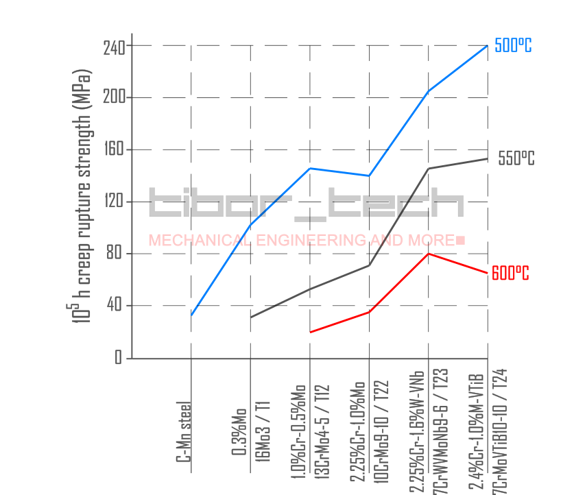
In the next part, we’ll discover the development of 9-12%Cr steels – yes, the X20 comes again. Stay tuned!
My Facebook group with many interesting engineering-related topics is waiting for you
