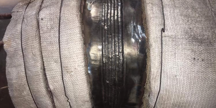
X20 is a notoriously tricky material. The room-temperature hardness of as-welded deposit metal exceeds 500HV10 over a wide range of cooling conditions, even if the cooling takes 2 hours. Welding such a material requires strict welding parameters, trained welders, and experienced welding engineers. This material was widely used in European power plants for almost 30 years. Besides the evolution of material science, which has delivered creep-resistant materials with much better weldability, it is worth getting familiar with X20.
The roots of X20
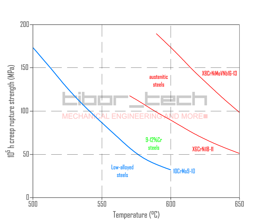
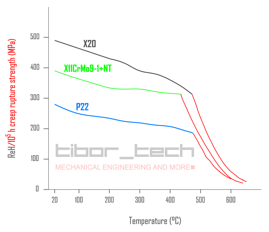
The roots of X20CrMoV12-1 go back to the 1920s. The 0.25%C-13%Cr alloy was the basis of various corrosion-resistant and high-temperature steels used for turbine blades and corrosion-resistant machine elements. The first trials with welding showed poor results, and material development concentrated on austenitic steels. 12CrMoV was widely utilized for forged turbine rotors and cast turbine casings. Higher efficiency requires materials with higher creep strength, especially for the live steam line. The gap between low-alloyed steels (Grades 11, 12, and 22) and austenitic materials was too high – Figure 1 – and a transition material was missing:
fter many welding trials, the breakthrough in 12CrMoV welding in manufacturing crack-free welds in 1959 opened the door for steam parameters of 212 bar and 560°C. After this breakthrough, the material was standardized for steam pipes under the DIN designation X20CrMoV12-1 and material number 1.4922. This material is known outside Europe as X20.
The X20CrMoV12-1 was first used in 1966 at Mannheim, West Germany. Its high creep strength allowed the construction of larger power plants in West Germany. This material was the basis of European power plants for three decades.
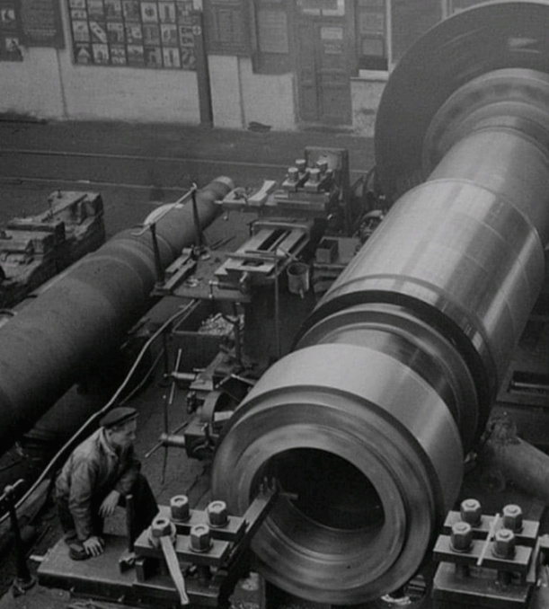
X20CrMoV12-1 was widely used in main steam lines, headers, forgings for turbine rotor (Figure 2), and its cast version G-X23CrMoV12-1f or turbine casings. Table 1 shows the chemical composition of different X20 variants. Besides the power plant application, this material was widely used in high-temperature chemical processes.
| EN designation / ASME designation Material number | Product type | C | Si | Mn | P | S | Al | Cu | Cr | Ni | Mo | V | W |
|---|---|---|---|---|---|---|---|---|---|---|---|---|---|
| X20CrMoV11-1+QT X20 1.4922 | Pipe (EN 10216-2) Forging (EN 10222-2) | 0.20 | 0.35 | 1.00 | 0.025 | 0.010 | 0.040 | 0.30 | 11.70 | 0.55 | 1.00 | 0.30 | – |
| GX23CrMoV12-1+QT _no_ASME_designation 1.4931 | Cast (EN 10213) | 0.23 | 0.40 | 0.65 | 0.020 | 0.010 | 0.020 | 0.30 | 11.70 | 1.00 | 1.10 | 0.30 | 0.50 |
Metallurgy of X20
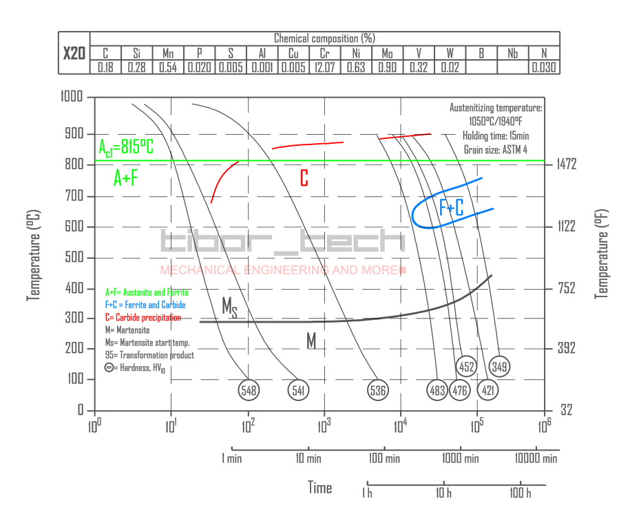
X20CrMoV12-1 is a steel alloy that requires a normalization temperature of approximately 1050°C. Cr23C6 carbides begin to precipitate between 900 and 700°C. If the base material’s thickness is less than 80mm, cooling it in air will create a martensitic microstructure. The martensite start (Ms) temperature is around 300°C. A longer cooling time between 750 and 600°C could result in Ferrite and carbide precipitation. Special cooling techniques are required for thicker sections to achieve the desired fully martensitic microstructure.
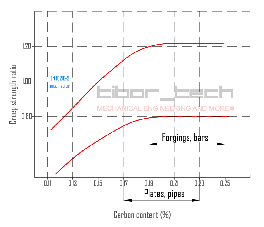
The high creep strength of this steel is primarily attributed to its fine microstructure with a high density of dislocations. At elevated temperatures, the dislocation density decreases due to relaxation, but precipitates on the grain boundaries prevent the microstructure from coarsening. This mechanism contributes to the steel’s structural stability and strength. X20CrMoV12-1 steel requires a minimum carbon content of 0.17% to achieve the necessary creep strength per EN 10216-2 – Figure 3. Structural stabilization through carbides is an optimal strength mechanism requiring minimum carbon content. This also explains why the material X11CrMo9-1+NT has significantly lower creep strength.
Tempering parameters (holding time and temperature) have an influence on the mechanical properties of X20. Tempering temperatures between 730 and 780°C are recommended as they lead to the formation of fine M23C6 carbides at sub-grain boundaries. This fine microstructure results in a high dislocation density, enhancing creep strength – Figure 4. However, as the material undergoes relaxation at service temperature, the dislocation density decreases and the fine microstructure exhibits grain coarsening.
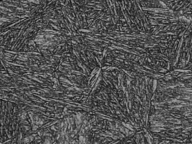
The microstructure of the X20 steel is tempered martensite – Figure 5 – formed during a final normalizing and tempering heat treatment. Deviation from the recommended heat treatment
conditions leads to changes in the microstructure. Standard cooling in air to room temperature results in a residual austenite of 2-5%, which is detrimental to long-term creep properties.
The forming temperature for any hot forming should be between 850-1100°C. After forming, the part should be cooled in air (no forced air cooling). Re-quenching should be performed with qualified heat treatment equipment. The parameters as per the material certificate or Table 2:
| Steps | Process | Temperature [°C] | Holding time [min] | Cooling agent: |
|---|---|---|---|---|
| 1 | Quenching | 1020-1070 | 1 minute per mm and a minimum of 30 minutes | Normal air (no forced cooling) NOTE: For extremely thick (>150mm) sections, accelerated cooling could be necessary |
| 2 | Tempering | 730-780 | 2 minutes per mm and a minimum of 120 minutes |
Cold bending on X20 is not recommended
Weldability of X20 – CCT diagram
Welding of X20 is notoriously tricky; it requires good workmanship and trained and experienced welding professionals. Due to its high C-content, X20 has a higher Ms temperature than the other creep-resistant steels. The high C-content results in a hardness of approximately 520HV10 in the as-welded condition. Most of the Codes (ASME, EN) require 350HV10 maximum hardness The challenges can be explained on the CTT diagram – Figure 6:
There are two types of practices for welding 9-12%Cr-containing heat-resistant steels:
- austenitic welding
- martensitic welding
Weldability of X20 – Austenitic welding
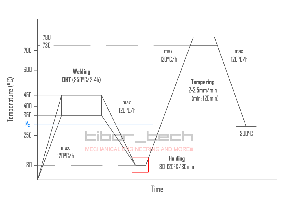
When applying austenitic welding, a preheating temperature of around 380-450°C, above the Ms temperature, is required to ensure that the parts of the welded joint and the heat-affected zone (HAZ) remain austenitic throughout the welding process. However, a higher preheating temperature is not recommended, as it can cause ferrite precipitation in the weld metal and HAZ, which decreases the joint’s strength and creep properties.
After welding, the joint should be cooled slowly at about 100-150°C/h until it reaches 100°C. This is necessary to transform the remaining austenite into martensite. The joint must be kept at this temperature for 30-60 minutes to equalize the heat. This process is known as intermediate cooling. Any additional cooling is not only unnecessary but can also be harmful due to thermal stresses.
To reach the tempering temperature, the welded joint must be heated at 100-200°C/h. If the joint is cooled immediately after welding and then tempered, carbide and ferrite precipitation can occur during the cooling of the remaining austenite.
Figure 7 summarizes the austenitic welding technique:
Weldability of X20 – Martensitic welding
Martensitic welding has an advantage over austenitic welding as it requires a preheating temperature that is 100-150°C lower. The welding process is carried out at a temperature below Ms to allow part of the austenite to transform into martensite during welding. This reduces residual austenite content as compared to austenitic welding. Consequently, internal stress resulting from tissue structural transformation is lower during cooling after welding.
As per experience, crack sensitivity is lower in martensitic welding than in austenitic welding, considering the entire duration of welding.
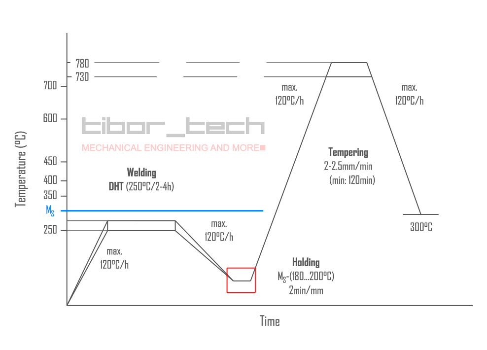
The key element of this welding technique is the optimal selection of the preheating temperature. The most suitable temperature for preheating and intermediate cooling is the temperature at which the ratio of austenite and martensite is 50-50%. Experience has shown that the optimal preheating temperature is around Ms – (50…70°C). The relation Ms – (180…200°C) determines the optimal intermediate temperature. The Ms temperature can be calculated with this empirical equiation (Prof. Béres, Hungary):
![]()
If the preheating temperature is higher than this, the proportion of remaining austenite is too high, increasing the stress from the phase transformation during the intermediate cooling. On the other hand, if the preheating temperature is lower than this, the risk of cracking increases as martensite has a lower specific elongation. It is less capable of absorbing deformations resulting from the phase transformation.
During the intermediate cooling phase, the hardness gradually decreases to 350 to 400 HV10 and only drops below 240 HV10 during tempering. The welded joint is still very brittle at this temperature, so it is not advisable to cool steels with more than 0.15% carbon to room temperature. Steels with a lower carbon content have higher toughness, which means that the preheating temperature can be lower, and cooling to room temperature before tempering is allowed. The recommended duration of heat retention at the intermediate cooling temperature is 2.0 to 2.5 minutes per millimeter.
The rate of the preheating temperature is usually 150 to 200°C per hour. This heating rate is recommended for both the cooling rate during intermediate cooling and the heating rate during hardening. The tempering temperature of X20 steels is 730 to 780°C, with the middle temperature being prescribed. The upper temperature is only necessary for wall thicknesses over 40 millimeters. The holding time during tempering is 2.0 to 2.5 minutes per millimeter and at least 60 minutes. Cooling is then carried out to 250 to 300°C at a maximum speed of 120°C per hour.
The crack sensitivity of martensitic welding is significantly lower – this is why this was the preferred method over austenitic welding.
Figure 8 displays the martensitic welding technique for X20:
Filler materials for X20
It is recommended that the alloy specified in Table 3 be utilized, as it matches the chemical composition and mechanical properties of the base material:
| Welding process | EN ISO | AWS | Gas / Flux |
|---|---|---|---|
| SMAW – 111 | 3581-A – E CrMoWV12 | ||
| GTAW – 141 | 21952-A – W CrMoWV12Si | A5.18 – ERS-B92 | EN ISO 14175 – I1 (100%Ar2) |
| SAW – 121 | 24598-A S CrMoWV12 | A5.23 – F9PZ-EG-G | Fluoride-basic type flux |
In situations where X20 steel needs to be welded in a rigid structure that allows for limited deformation, it is recommended to use NiCr3 (70%Ni-20%Cr) welding material.
Dissimilar welding of X20 requires special considerations.
Summary
X20 was one of the most challenging types of steel to weld for several decades. Skilled and experienced welding professionals were required to handle it properly. Proper heat management was crucial to achieving the requested impact values and creep strength. The new-generation 9%Cr steels, such as P91, are more user-friendly due to their lower carbon content. However, they are still considered difficult materials to work with…
